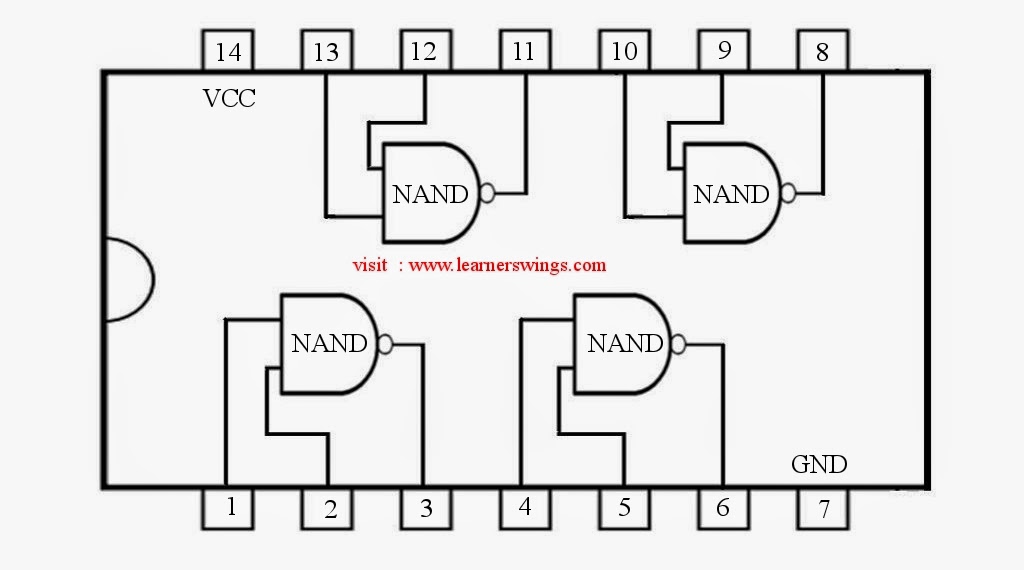
Nand Gate Diagram
Digital logic nand gate – universal gate Vhdl tutorial – 5: design, simulate and verify nand, nor, xor and xnor Nand gate circuit diagram circuits inputs input electronic through pull down explanation button connected then power
Conversion of NAND gate to Basic gates
Nand boolean Vhdl tutorial – 5: design, simulate and verify nand, nor, xor and xnor Gate xor xnor nand nor vhdl verify simulate engineersgarage circuits dummies transistor inverter scosche ckt
Gate nand logic universal nor function digital into given made basic electrical which other below figure
Nand gate circuit diagram and working explanationIntroduction to logic gates Digital logic nand gate(universal gate),its symbols & schematics74hc00 / 74hct00, quad 2.
Nand gate diagram circuit ic 74ls00 pinout gates logic circuits chip not input circuitdigest working diagrams explanation electronic using limitationsDigital lab Nand gates conversionIntroduction to logic gates.

What is nand gate and gate
Vhdl tutorial – 5: design, simulate and verify nand, nor, xor and xnorNand gate nmos logic schematic transistor using digital universal ic symbols its two given below Nand gate logic gates truth table output introduction technology if only transistor complement its inputs lowGate nand nor xnor circuit vhdl xor logic simulate verify circuits ckt wiring engineersgarage.
4011 nand circuit pinout datasheet integrated basic circuitsNand gate circuit diagram and working explanation Nand xor logic nor gates xnor circuit vhdl simulate verify truth input circuits tutorial engineersgarage inverter scosche inputs ckt combinedConversion of nand gate to basic gates.

Nand gate diagram 74hc00 ttl input quad 7400 pinout latch using gates nor push pull octoprint get funny four has
Nand logic projectiot123 input nor symbols complement inputs .
.


NAND Gate Circuit Diagram and Working Explanation

74HC00 / 74HCT00, Quad 2 - Input TTL NAND Gate. Pinout Diagram « Funny

VHDL Tutorial – 5: Design, simulate and verify NAND, NOR, XOR and XNOR

Conversion of NAND gate to Basic gates

Digital Lab - Basic 2-Input NAND Gate Circuit | Digital IC Projects

Introduction to logic gates

VHDL Tutorial – 5: Design, simulate and verify NAND, NOR, XOR and XNOR

Digital Logic NAND Gate(Universal Gate),Its Symbols & Schematics

VHDL Tutorial – 5: Design, simulate and verify NAND, NOR, XOR and XNOR